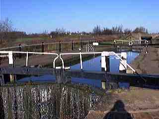
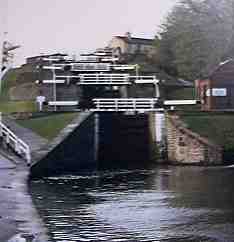
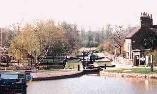
A pound lock on the Grand Union canal at Stoke Bruerne
Early inland waterways were simply natural rivers. Boats could not travel far inland, and could go uphill only by going up the slight gradient of a flowing river. The range could be extended by building a temporary dam downstream of the boat, and waiting for the level to rise. This system was made easier by "flash" locks, where the dams were replaced by permanent structures with removeable sections. Such structures could also be used by riding the rapidly-moving water pouring through the open gap, or bow-hauling up through it, saving the wait for the whole reach to adjust. Even so, this was inconvenient and hard work, and it did not please the owners of watermills who were concerned about their levels being changed to facilitate navigation. This was solved by the introduction of the "pound" lock, which allowed boats to move between levels easily, without upsetting the general levels of the river, and without great delays. The invention of this type of lock also allowed the construction of canals, waterways independent of natural rivers.
The defining feature of a pound lock, as found on all modern canals, is a chamber, just large enough for the largest vessel, with gates at both ends. With this arrangement, when a boat wants to pass from one level to another, only the relatively small volume of the chamber need be filled, rather than a whole reach.
A pound lock on the Grand Union canal at Stoke Bruerne
The operation of a lock can best be seen by following the operations as boats are transferred from one level to another. Suppose we have a lock, with one boat waiting to go up, and one waiting to go down. Let us start with the lock chamber empty. Then, it is possible to open the gates at the lower level, and for the boat waiting to go up to move into the chamber. The gates are closed behind it. The lock is then filled, by taking water off the higher level. In most locks, this is done by pipes running past the upper gates, which are normally blocked by wooden panels called paddles; when the paddles are raised the water is able to flow. When the lock is full, the upper gates can be opened, and the boat can leave, making room for the boat waiting to go down. The paddles at the upper end, meanwhile, have been closed. With the boat in the chamber, the upper gates may be closed, and the level lowered again by raising a second set of paddles at the lower end; often these paddles simply cover square openings in the gates, below the waterline. When the chamber is empty, the lower gates may be opened, the paddles closed, and the boat may go on its way. With the closing of the lower gates, the lock is back as we found it.
Without any serious effort on our part, the lock has raised one heavy boat to a higher level, and lowered another. The effort has come from the water, some of which has been taken off the higher level and added to the lower. How much water?
In measuring the water usage of any system, it is important to make sure that no water is missed, and no water is counted twice. Some accounts, even in respectable books, fail to ensure this. My method is to define a reference surface, intersecting the canal, and to measure the flow through this surface and nowhere else. To see how this works, consider the ordinary lock, and take the vertical surface across the line of the canal, through the top gates and extending outwards.
Start, as before, with the lock empty. The first operation is to fill the lock, through the top paddles. Whether these are conventional ground paddles or gate paddles, the water flows from the top level into the lock, which are on opposite sides of our surface, so we count this water, one lockful. When the first boat leaves, the second enters, and the lock is emptied, there is no flow through our surface. So for one complete cycle, one boat up and one boat down, one lockful of water is used.
If the canal is operating at its maximum efficiency, every lock cycle will take one boat up and one boat down, an average of half a lockful per boat. In practice, often there is no boat wanting to go the other way, and then the whole lockful is used for one boat. The average is somewhere in between. If this water cannot be replaced at the upper level, from reservoirs or from rivers or streams, the canal cannot continue to work. In extreme cases, pumps may have to be used, to return water from lower levels back past the locks to the upper levels.
When a canal uses a series of simple locks to overcome a greater height difference than a single lock can achieve, then the water that leaves one lock at its lower level appears at the upper level of the next lock below. In this way, the same lockful of water can raise one boat and lower another at each lock in the series (assuming the locks are all of the same size).
Typically, a canal will rise from a river valley, cross a summit, and descend into another valley, with a series of locks on both sides. For a complete transit of such a canal, a boat will use its average half-lockful for the ascent to the summit, and then another half-lockful to go down the other side, so at best, each boat that goes end to end uses one lockful of water. At worst, if the locks cannot be worked alternately, each boat will use two lockfuls of water.
For most practical purposes, the water consumption of a simple lock is one lockful per cycle, but in fact this is only an approximation. In any real canal, leakage must be a big factor, although I am going to ignore it here because it is not very interesting. Also, if the locks in a series are not all of the same capacity, then the level below a large lock and above a smaller one will tend to become full, and excess water must be disposed of. The level below a small lock and above a larger one will tend to become empty and extra water must be supplied. It may be possible to allow the excess water in one level to bypass the lock below, over a weir, and supply a falling level below, but I am not convinced that it is possible to keep all levels correct like this without wasting water by weiring unnecessarily. Often, a canal will have deeper locks at its lower levels, as it is usually easier to find extra water here than at the summit.
The most interesting error in our water usage is not really relevant to the simple lock, but will be important in the discussion of locks with side ponds. However, I introduce it here as it applies to the simple lock. By Archimedes Principle, anything that floats displaces its own weight of water, and this applies to boats. When a boat goes into a lock, it displaces some of the water in the lock, so when a boat enters the lock at the top level for example, there is a flow of water past the top gates in the opposite direction to the boat back onto the top level.
Let us rework the simple lock using mathematical notation, with Wu as the weight of the boat going up, Wd the weight of the boat going down, and Wlock the weight of one lockful of water. To keep the notation simple, I'm going to measure weights in kilograms-force, which I'm going to call, loosely, kilograms. Over the same cycle as before, and with the same reference plane, we find:
| operation | flow off top level |
|---|---|
| boat 1 enters lock | zero |
| lock filled | Wlock |
| boat 1 leaves lock | Wu |
| boat 2 enters lock | -Wd |
| lock emptied | zero |
| boat 2 leaves lock | zero |
| TOTAL | Wlock + Wu - Wd |
So the water usage is slightly different from one lockful, and the difference is the difference in weight of the boats. If the lock is generally passing net weight uphill, it uses slightly more than a lockful, and if generally downhill, slightly less than a lockful.
To put this in context, let's try a few figures, for a typical narrow lock. Let's assume the lock is 22m long by 2m wide by 3m deep, a volume of 132m 3, and a weight of 132 tonnes. A laden narrowboat might weigh 30 tonnes, and an empty one 10 tonnes. So a lock working full boats up and empty ones down would use 152 tonnes of water per cycle, and one working the other way 112 tonnes per cycle.
The lock may be considered as a mechanical machine, it is after all raising and lowering heavy loads, just as crane might do; it takes in energy, in the form of water stored at a high level, and uses it to move loads up and down. How efficient is it? In terms of ease of construction, and ease of use, the lock is a very convenient system, but in its basic form it is not very efficient as a machine, measured as the useful work output as a fraction of energy taken in.
A basic law of physics, called Conservation of Energy, is very useful in simplifying complex problems. Roughly, it states that energy can be moved from place to place, it can be transformed from one form to another, but it cannot be created or destroyed. From this may be deduced that no machine can give out more energy than it takes in, except by depleting some internal store that must ultimately run out, and that if a machine appears to give out less than it takes in, it must either be storing it, or more likely transforming the losses into some less useful or less obvious form.
The energy supply into a lock is in the form of potential, or gravitational, energy, contained in water at a high level, which can be extracted by allowing the water to fall to a lower level; the amount of energy which is taken out by a transfer from one level to a lower level is given by the product of the weight of water and the height difference.
In our example lock cycle above, by conservation of energy, a maximally efficient lock would move up or down a weight of water exactly equal and opposite to the difference in the weights of the two boats. Then the potential energy extracted from the water in moving down by the difference in levels would be exactly equal to the net energy given to the boats in moving up the same distance. In fact, as we have seen, the lock uses precisely this much water, plus one lockful over.
So, no matter what traffic the lock is carrying, it always wastes the energy in one lockful of water for each complete cycle. This energy loss is responsible for part of the fascination with watching locks, as most of it goes first into kinetic, or motion, energy of the water as it flows past the paddles, and then as the water thrashes and swirls, it is converted to heat energy in the water, and a little sound energy. As the lock is filled, the ferocity of the motion of the water reduces, as if the first part of the water has to fall all of the way to the lower level, and the last part falls hardly at all; we might say that the average fall is one half of the level difference. This argument, and symmetery, suggest that half of the energy is converted as the lock is filled, and the rest as the lock is emptied.
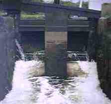
White water as a lock is filled
How much hotter does that water get? Our example lock dropped 132 tonnes of water by 3m, extracting energy of 396 tonne-metres, or about 4 MJ. Half of this appears as heat in the water when the lock is filled, spread out in about 200 tonnes of water (there is some water in the chamber even at the lower level) or 10 J/kg. Given water's heat capacity of about 4000 J/kg/K, the temperature rise would be about 0.003 degC. Not much!
{Wrinkle: We've not taken into account the fact that the top and bottom levels actually have depth - what if the water flows from the bottom of the top level to the top of the bottom level, does that mean less energy is involved? No, because the energy of a given particle of water is the same whatever depth it is at, it is determined only by the height of the surface. At the surface, it has a certain gravitational energy; if it descends it loses gravitional energy but aquires pressure energy, effectively it is slightly squashed against its elasticity so that its total potential energy is the same. The energy that can be got from water with its surface at a certain level is the same whether we let it flow slowly from the top of the reservoir and drop, or squirt it out under its natural pressure from the bottom.}
When a canal must make a change in level greater than can be achieved in a single lock, several may be used in series, each using the water discarded by the lock above, so that the whole series uses the same quantity of water as a single lock. These locks may be spaced out in singles with a fair distance between, where the canal crosses gently sloping country, or they may be grouped closely together in a "flight". Putting locks togther in one place also helps to reduce the time taken in working locks, and makes it easier to supervise them, so newer canals tended to prefer this arrangement if possible.
Grouping locks into a flight makes no difference to the theory of operation, but it does make some points more obvious. As the pounds between the locks become shorter, and therefore able to contain less water, the changes of level as the locks are filled and emptied become more obvious. Good practice is to, whenever possible, open the top paddles of the lock below before or just after opening the bottom paddles of the lock above, making sure that the water follows the required path through the locks, and does not get wasted over the bypass weirs that regulate the levels in the intervening pounds. Normally in a flight, the pounds between the locks are big enough to allow boats to pass, so that it is still possible to alternate in each lock.
Where space is very limited, locks in a flight can be placed so close togther that the intervening pound is reduced to a narrow passage, of the same width as the lock chamber. To regulate the level of this tiny pound, it must be connected through a culvert to an adjacent reservoir, called a side pond. This arrangement still follows the same theory as a conventional flight, but is on average less economical with water. This is because boats cannot pass in the flight, so it is difficult to alternate in each lock. It is easier to work the flight so that several boats go down one behind the other, then several are brought up, making the average consumption nearer to a whole lockful per boat than the minimum half lockful. If one boat comes down the entire flight, then one goes up, then another comes down, and so on, only a half lockful would be used, but this would be very time-consuming.
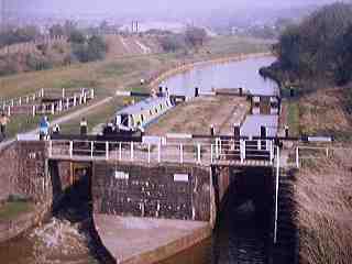
This arrangement is very rare, but a good example is The Bratch on the Staffs & Worcs Canal, where there is a flight of three.
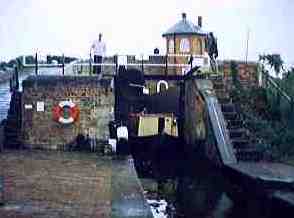
The Bratch.
(Notice the two sets of gates between the chambers: double gates for the upper lock (manned by myself and my father) and a single gate for the lower lock.)
Where locks have to be placed very close togther, a more common arrangement is a staircase. A staircase looks very similar to a set of joined locks, but the big difference is that there is only one set of gates between each chamber, so that the top gates of one lock are also the bottom gates of the lock above. This makes a strong visual impression when viewed from a boat entering at the low level; you see the lock side above you as usual, but in front you see a huge gate, towering up to the upper level, not of your lock, but of the lock above. In place of the pound between the two locks, the level is determined by a side pond, which is connected by separate culverts to the top paddles of the lower lock and to the bottom paddles of the upper lock.
To follow the operation, let's imagine a two-lock staircase, and start with both chambers empty. We'll count the water, as before, through the line of the top gates of the top lock. A boat enters the bottom chamber and the gates are closed. The bottom lock is then filled from the side pond, and the top chamber is also connected to the side pond so that the levels can become exactly equal, at which point the central gates are opened and the boat moves to the upper chamber. With the gates closed again, and the central paddles all closed, the upper paddles are opened and the top chamber filled, taking one lockful through our reference surface. The boat can now leave, and be replaced by another going down. The lower chamber is re-connected to the side pond, then the top chamber emptied into the side pond. The boat moves to the lower chamber, which is then emptied into the lower level of the canal.
So, just as for the linked locks, one boat up and one boat down, one complete cycle getting back to the same state, uses one lockful. However, just like the linked locks, it is time-consuming to work like this, and taking the easy path of allowing boats to follow down the staircase uses more water per boat, up to one lockful.
Staircases of this type may be found at Foxton, on the Grand Union Leicester Arm, where there are two flights of five with a passing bay between, and on the same canal at Watford, where there is a flight of four.
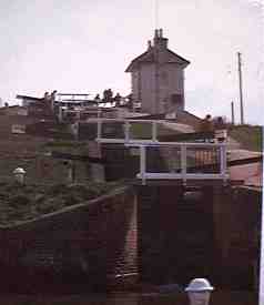
The upper half of the Foxton staircase
It is possible to employ a staircase without any side ponds, though it is more difficult to work. As there is no storage of water at the intermediate levels, careful use of the paddles is required to get water where it is needed. This is often made more difficult in practice, where leakage and small differences in the actual volumes of the chambers mean that the lock operator has to keep his wits about him, and add or subtract water as required. There are paddles connecting the top of the top chamber to the canal upper level and the bottom of the bottom chamber to the canal lower level. The other paddles link the top of one lock to the bottom of the lock above.
The principle can be seen by thinking about a two-chamber arrangement. As usual, let's take one boat up and then one down, starting with both chambers empty. To work this type of staircase, it is essential to follow the rules: (1) to go up, start with all chambers except the bottom one full; (2) to go down, start with all chambers except the top one empty. Failure to follow these rules can result in serious flooding. For our case of two chambers, we must first fill the top chamber, taking one lockful through our surface. The boat can then enter the bottom chamber. Opening the middle paddles then allows the full top chamber to flow into the empty lower chamber, until a level is made, at which point the lower chamber is full and the upper chamber empty, and the boat can move to the upper chamber. It is then raised to the upper level by filling the top chamber from the upper level, taking a second lockful. To comply with the rules, for the next boat to descend, we must first empty the bottom chamber. Then the boat can enter the top chamber, and empty that into the lower chamber, then empty that chamber and descend to the lower level, leaving both chambers empty as we started. So to alternate two boats has taken two lockfuls, not one. Saving the complexity of the side ponds has not only made operation more complex, but also wasted water.
After a boat has gone down, all chambers are empty, so all that a following boat has to do is to fill the top chamber and start down. Following boats use one lockful each, just as for ordinary locks, or staircases with side ponds.
Now imagine a longer staircase, let's say a five-chamber one, such as Bingley Five-Rise on the Leeds & Liverpool Canal. Suppose a boat has just come down, so that all chambers are empty, and a boat wants to go up. By the rule, the top four chambers must be filled. The lock-keeper (Barry) starts at the top of the flight and walks down opening all the paddles as far as the ones at the top of the second-last chamber, then, as each chamber fills, comes back up, closing the paddles as he goes, until the top chamber is filled and all paddles closed. This uses four lockfuls of water. The boat may then enter the bottom chamber, and ascend the flight by emptying each chamber in turn into the one below. For the final rise to the upper level, a final, fifth lockful must be drawn. No more water is used if the cycle is reversed to take a boat down, so to alternate at Bingley takes five lockfuls per cycle, or two-and-a-half per boat.
As with the two-chamber system, following boats still need only one lockful each, so here it is much more efficient both in time and water to run streams of boats in one direction. The huge extra water requirement may be thought of as required to change the direction of the locks.
What's the simple, fundamental reason why the lack of side ponds make a Bingley-type staircase so much less water-efficient than a Foxton-type? I'm still thinking.
Bingley Five-Rise Staircase
Boat lifts have been tried in a few places in Britain, though none is currently operating, and, on a larger scale on the European continent, where some are still in use. Lifts have the advantage of being very ecomonical with water, but are much more complex mechanically.
Boat lifts may be wet or dry. Dry lifts have been used with small, light boats, but are not of much interest, they are little more than cranes that lift boats from one canal to another. Wet lifts transport boats while still afloat, and make use, again, of Archimedes Principle, which here gives us the important corollary that a caisson full of water with a boat floating in it weighs exactly the same as a caisson full of water with no boat in it. This allows a boat lift to be finely counterbalanced, so that the only mechanical effort that needs to be put in is to overcome friction.
Of the two famous lifts in Britain, one was a vertical lift, at Anderton, and one was an inclined plane, at Foxton. Both had two caissons connected together by ropes so that as one rose the other fell. Both the caissons and the ends of the short connecting arms from the canal upper levels had gates and seals, so that the only water lost on each operation was the small amount caught between the two gates as the caisson moved away from the top level. At the lower level, it is possible for the caisson to go right into the lower level of the canal, rather than needing another set of gates and seals.
Wet boat lifts waste very little water, just the leakage and the loss of the gap water mentioned already. The water budget, for one caisson through one cycle, is:
| operation | flow off top level |
|---|---|
| boat 1 enters caisson at lower level | zero |
| caisson raised | zero |
| boat 1 leaves caisson at upper level | Wu |
| boat 2 enters caisson at upper level | -Wd |
| caisson lowered | zero |
| boat 2 leaves caisson at lower level | zero |
| TOTAL | Wu - Wd |
Because of the effect of water displaced by a boat entering a caisson, a lift always transfers a weight of water equal to the difference in weight of the boats in the two caissons in the opposite direction, so if, on average, the boats going down are heavier than the ones going up, then water goes up to compensate. Lifts thus do not waste energy either, the potential energy given to the boats is the same as the potential energy taken from the water, or vice versa; this is also apparent from the absence of energy-dissipating thrashing water.
The Anderton lift was later converted so that each caisson was driven separately, counterbalanced by fixed weights, but this did not change the principle. It is a little less elegant, as, if the level of the canals changes, the counterbalancing cannot be so precise.
Lifts were generally not satisfactory, both because of the complexity, and because of the need to keep power plant available to drive them, which was especially difficult with steam power when the traffic was intermittent.
[The Anderton lift has recently been restored; it is now operated hydraulically but the caissons are still independent. There is also a brand new boat lift at Falkirk in Scotland with two caissons slung between two large wheels. And there is talk of restoring the Foxton lift.]
Locks waste water, but are simple and durable; lifts don't waste water, but are costly and temperamental. Is there a better compromise?
Yes. Locks with side ponds can be designed to reduce water consumption, at the expense of increased complexity, and they have proven much more successful than lifts; though few are operating today in Britain, they are used on modern commercial waterways.
To see the principle, consider a lock with a single side pond. This lock looks just like our simple lock, except that there is an extra set of paddles, connecting the lock chamber through a culvert to a large reservoir alongside the lock, kept at about the half-way level. Let's take this through one cycle, and count the water used:
| operation | flow off top level |
|---|---|
| boat 1 enters lock | zero |
| lock half-filled from side pond | zero |
| lock filled from top level | Wlock/2 |
| boat 1 leaves lock | Wu |
| boat 2 enters lock | -Wd |
| lock half-emptied to side pond | zero |
| lock emptied to lower level | zero |
| boat 2 leaves lock | zero |
| TOTAL | Wlock/2 + Wu - Wd |
This returns us to the original state, with the chamber empty, and the side pond with the same amount of water, using only half a lockful, a huge improvement.
Atherstone top lock, Coventry Canal.
(The side pond is the railed-off chamber to the left of the lock. It is out of use, and its paddle used to be in the centre of the railing nearest the lock.)
What's more, as more side ponds are used, the wasted water gets less, though the saving is less for each extra side pond. Generalising the argument above, the water used for a lock with N equally-spaced side ponds would be:
| operation | flow off top level |
|---|---|
| TOTAL | Wlock/(N+1) + Wu - Wd |
Incidentally, the level in the side pond is maintained automatically. If the level becomes slightly low, then less is taken out to part-fill the lock on the way up than is returned by part-emptying it on the way down, so the level is increased on each operation until it reaches half way again.
Adding the first side pond saves a half lockful, the second saves a further one-sixth, the third saves a further one-twelfth. Where the system was used on British locks, one or two was the usual choice. Some Grand Union locks have two side ponds, though these are derelict at present.
A variation on the single side pond system is to use two complete locks side by side, with a paddle linking the two chambers; if the locks are worked alternately, one up as the other goes down, then this is equivalent to two locks each with one side pond, as can be seen by working the pair through one cycle, starting with one empty and the other full, and four boats waiting:
| operation | flow off top level |
|---|---|
| one boat enters each lock, one up one down | -Wd1 |
| both locks brought to half-full by connecting them together | zero |
| one lock filled from top level, and the other emptied to the lower level | Wlock/2 |
| boats leave locks | Wu1 |
| two more boats enter | -Wd2 |
| both locks brought to half-full by connecting them together | zero |
| one lock filled from top level, and the other emptied to the lower level | Wlock/2 |
| boats leave locks | Wu2 |
| TOTAL for both locks | Wlock + Wu1 - Wd1 + Wu2 - Wd2 |
So two locks have been cycled for one lockful of water; half a lockful each, the same as a lock with a single side pond.
A double lock on the Trent and Mersey Canal
(though being used as two singles in this picture)
Though side ponds use no more exotic technology that conventional locks, they have generally fallen into disuse. This is probably because, to the individual boat user, there is no advantage, only extra work and extra time taken. Unless the locks are supervised, the side pond paddles are likely to be ignored, and the advantages lost. With some large locks on Continental commercial waterways, the side ponds are controlled by computer, so that their use is assured at all times with no extra effort.
Why are side pond locks more efficient? As the number of side ponds is increased, the water consumption approaches the same level as a lift, just the water needed by the Conservation of Energy, so the losses must be reduced. This is seen in the operation. Because water is only ever run between levels close together, there is less swirling and thrashing, and less energy dissipated as heat and sound. This also means that the operation is likely to take longer, as the water is, on average, moving more slowly.
If the number of side ponds is made very large, approaching infinity, then the lock's water consumption becomes the same as a lift's. But the water flow would become very slow, always like that last centimetre that seems to take for ever. But even with four or five side ponds, it is possible that the lost water is less than the water flow needed to satisfy the energy equation, so that the lock might actually pump some water up when a heavy boat goes down.
This note led to a discussion on uk.rec.waterways around 2014-Feb where many doubted the analysis here. A more detailed diagrammatic explanation of the basic lock operation is given here.
