THE KGS 1
DIGITAL COMPUTER
The K.G.S.1 digital computer performs simple calculations in binary arithmetic simulating the working of a full scale digital computer, although the actual calclations it can perform and the speed with which it performs them is strictly limited. In this computer a 1 digit is represented by a negative potential or a light on, and a 0 digit by zero potential or the light off.
The K.G.S.1 can conveniently be divided into three basic units: the control unit, the storage unit and the calculating unit.
These three units are linked in two ways:
1 by a wire called the main bus which carries binary digits from one unit to the other, and
2 by four wires which are used to alter the state of relays in the storage and calculating units corresponding to the program being fed in.
THE STORAGE UNIT
The storage unit contains sixteen stores each of which can store a binary digit, and circuits (called the gating circuits) which enable any one of those stores to be connected to the calculating unit individually. The lights corresponding to the stores, showing whether they are on or off (i.e. storing a 1 or 0) are arranged in a square and for convenience are given letter-names s to z and s' to z' as in the diagram:
For the purposes of programming it is necessary to have names for the stores which are binary numbers, although these numbers infer nothing about what is stored in a particular store of the meaning of a digit stored there; they are just names for the stores which can be used to set the input relays A,B,C,D (for instance for store 1011 A,C and D would be set but not B), and these would be used to set corresponding relays in the gating circuits which would connect the store with that name to the main bus. The name for any store can be found easily from the diagram by taking the two digits at the end of the horizontal line it is in as the first two digits of its name, and two for the vertical line for the last two; for example, y would be 0110; x' would be 1101.
THE CALCULATING UNIT
This unit can accept two binary digits and perform one of a number of different calculations on them depending on the state of four relays A2,B2,C2,D2 in the construction of its circuit. The two input binary digits p and q set the two relays P and Q. For example, if p=1 and q=0 then the P relay is set but the Q relay stays relaxed.
When the required circuit has been selected by activating the right combination of A,B,C,D then the output r aong the main bus will be determined by the state of the P and Q relays.
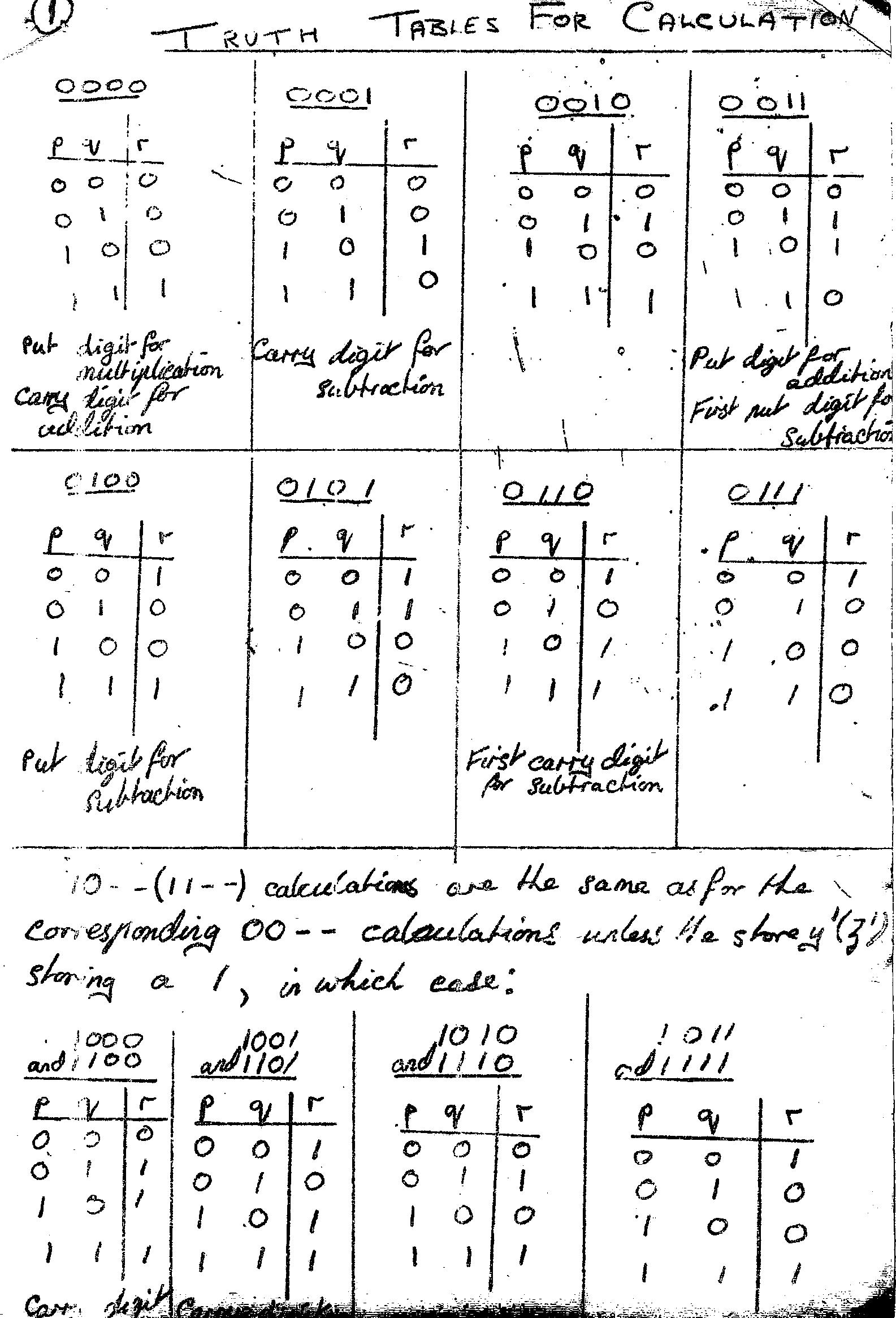
Just as with the storage unit, the state of the relays A,B,C,D depends on the program being fed into the control unit. Suppose, for example, the input to the control unit at a particular stage in the program consists of A and B off and C and D set and this is then transferred to the A,B,C,D relays of the calculator. It is convenient to express this input as the four-digit binary number 0011 although it is an instruction to the computer. The calculating unit can now perform one of its eight basic functions, the 00-- and 01-- programs (10-- and 11-- programs will be dealt with later). To see what it does we can write down the truth table for the inputs p and q and output r:

This 0011 program will be recognised as that for the 'put down' digit for addition. The tables for other inputs are given separately, although the table for the 0000 program is put down since it is relevant to the later discussion as the 'put down' digit for multiplication of the carry digit for addition.
THE CONTROL UNIT AND OPERATION OF THE COMPUTER
This unit is based around a rotary switch which has six stable states and turns from one state to the next every time it is given a negative potential. Using this switch it has been possible to connect the storage unit, the calculating unit and the program input in six distinct ways. Because of this the input has to be translated in different ways depending on which state the rotary switch is in. The program is broken down into cycles of six stages corresponding to each of the states (the data has been set into the stores before running the program) as follows:
STAGE 1 The program input a,b,c,d is connected to the storage unit but not to the calculating unit and the main bus travels from the storage unit to the P relay in the calculating unit. This means that the input a,b,c,d determines the particular store which is to be connected with the calculating unit and the state of this store determines the state of the P relay.
STAGE 2 This is almost the same as stage 1, except that the main bus now connects a store to the Q relay of the calculating unit so that the input a,b,c,d now determines the store which is to be linked to the Q relay.
STAGE 3 The input a,b,c,d is now connected to the calculating unit and not to the storage unit so that the input determines which calculation the computer will make.
STAGE 4 The input a,b,c,d is reconnected to the storage unit and disconnected from the calculating unit while the main bus now connects the output from the calculating unit to the storage unit. The affect of this is that the input determines into which store the result of the calculation shall go.
STAGE 5 This stage is mainly intended for use with supplementary instructions later. At present a 0000 input can be used each time. Also during this stage the calculating unit is reset ready for the next cycle.
STAGE 6 The input determines a store which will be emptied (i.e. reduced to storing 0). This is normally the store to be used for the result of the next calculation, although for the last cycle it can be any store not in use.
The computer is operated by a number of push-switches. Any store can be set (i.e. made to store a 1 digit) by pressing the corresponding switch in the set of sixteen, or emptied (made to store a 0 digit) by doing this while switch H is held down. The switch L controls the rotary switch (uniselector) which moves round one position each time L is pressed and so can be moved to the starting position for setting data. The program can then be run by pressing the required combination of A,B,C and D according to the four-digit input code in the program then pressing L, then the next input code then L, and so on. A,B,C and D d not need t be held down as they set and are reset when L is released.
To see how a calculation is performed the program for the addition of two binary digits n1 and n2 to give n”n' is given below in detail. The contents of the first eight stores (0000 to 0111, s to z) are given; the other stores are not used in this program.
|
Data input |
n1 -> s (0000) n2 -> t (0001) |
|
|||||||||
|
|
|
input |
|
contents of stores |
|||||||
|
cycle |
stage |
code |
details of program |
s |
t |
u |
v |
w |
x |
y |
z |
|
1 |
1 |
0000 |
n1 -> calc. unit |
n1 |
n2 |
0 |
0 |
0 |
0 |
0 |
0 |
|
|
2 |
0001 |
n2 -> calc. unit |
n1 |
n2 |
0 |
0 |
0 |
0 |
0 |
0 |
|
|
3 |
0011 |
put down digit n' for n1+n2 is calculated |
n1 |
n2 |
0 |
0 |
0 |
0 |
0 |
0 |
|
|
4 |
0111 |
n' stored in z |
n1 |
n2 |
0 |
0 |
0 |
0 |
0 |
n' |
|
|
5 |
0000 |
reset |
n1 |
n2 |
0 |
0 |
0 |
0 |
0 |
n' |
|
|
6 |
0110 |
store y is emptied |
n1 |
n2 |
0 |
0 |
0 |
0 |
0 |
n' |
|
2 |
1 |
0000 |
n1 -> calc. unit |
n1 |
n2 |
0 |
0 |
0 |
0 |
0 |
n' |
|
|
2 |
0001 |
n2 -> calc. unit |
n1 |
n2 |
0 |
0 |
0 |
0 |
0 |
n' |
|
|
3 |
0000 |
carry digit n” for n1+n2 is calculated |
n1 |
n2 |
0 |
0 |
0 |
0 |
0 |
n' |
|
|
4 |
0110 |
n” stored in y |
n1 |
n2 |
0 |
0 |
0 |
0 |
n” |
n' |
|
|
5 |
0000 |
reset |
n1 |
n2 |
0 |
0 |
0 |
0 |
n” |
n' |
|
|
6 |
0011 |
store v is emptied |
n1 |
n2 |
0 |
0 |
0 |
0 |
n” |
n' |
If larger numbers are added, four cycles are needed for each column except the first and the last as the carry digit from the previous column has to be added in. The first two cycles would add the first two digits for put down and carry; the next two would then add this put down digit to the third digit for put down and carry. The results from both carry calculations can be put into the same store as they cannot both be ones.
For subtraction (A-B) A and B being in binary notation it is easiest to regard this as A plus the true complement of B. The true complement of a number is formed by changing all of the 0s to 1s and vice versa, and then adding one to the result.
In the computer it is necessary to find calculations which give, for the units column, the put and carry digits for 1+p+q (where q means not q, i.e. 1 if q is 0, 0 if 1), these are calculations 0011 for put and 0110 for carry. For the other columns the calculations for put and carry for p+q are 0100 and 0001 respectively. The carry digits from the previous column can then be added as in the addition program using calculations 0011 and 0000.
THREE DIGIT CALCULATIONS
The programs so far described would be considerably simplified if calculations could be performed using three digits at a time (in many cases reducing four cycles to two). As increasing the number of stages per cycle would create other difficulties the calculating unit was extended so that 10-- and 11-- calculations would use three digits, the third digit always being that in store z'. However, this only reduced the four cycles to three as the result from a three-digit calculation could not itself be fed to z' ready for the next calculation. So the calculating unit was altered once more so that 10-- calculations used y'. This means that for normal addition or subtraction the carry digits can be put alternately into y' and z'.
The three-digit calculations are used as follows; the method of using Y' for the third digit will be given, with the difference for Z' in the brackets. When a 10-- (11--) program is in stage 3, if Y' (Z') is storing a 0, then the result will be the same as for the corresponding 00-- calculation; if Y' (Z') is storing a 1, then the result will be as shown in the relevant table of the last four. For the put and carry digits in addition and the carry digits in subtraction, these are the correct results if there is a carry of 1 from the previous column It should be noted that there are no three-digit calculations corresponding to the 01-- programs and so none for the “put” digit in subtraction.
As an example a program to add two numbers three digits long to produce the four-digit result is given. The stores used for the data and the result are shown by:

Any combination of stores could be used, but this method has the two original numbers on the first two rows of lights and their sum in the logical position on the next row.
|
CYCLE |
STAGE |
INPUT CODE |
|
|
1 |
1 |
0011 |
|
|
|
2 |
0111 |
|
|
|
3 |
0011 |
FIRST PUT DIGIT TO V' |
|
|
4 |
1011 |
|
|
|
5 |
0000 |
|
|
|
6 |
1111 |
|
|
2 |
1 |
0011 |
|
|
|
2 |
0111 |
|
|
|
3 |
0000 |
FIRST CARRY DIGIT TO Z' |
|
|
4 |
1111 |
|
|
|
5 |
0000 |
|
|
|
6 |
1010 |
|
|
3 |
1 |
0010 |
|
|
|
2 |
0110 |
|
|
|
3 |
1111 |
SECOND PUT TO U' (Using carry in Z') |
|
|
4 |
1010 |
|
|
|
5 |
0000 |
|
|
|
6 |
1110 |
|
|
4 |
1 |
0010 |
|
|
|
2 |
0110 |
|
|
|
3 |
1100 |
SECOND CARRY TO Y' (Using carry in Z') |
|
|
4 |
1110 |
|
|
|
5 |
0000 |
|
|
|
6 |
1001 |
|
|
5 |
1 |
0001 |
|
|
|
2 |
1010 |
|
|
|
3 |
1011 |
THIRD PUT TO T' (Using carry in Y') |
|
|
4 |
1001 |
|
|
|
5 |
0000 |
|
|
|
6 |
1000 |
|
|
6 |
1 |
0001 |
|
|
|
2 |
0101 |
|
|
|
3 |
1000 |
THIRD CARRY TO S' (Using carry in Y') |
|
|
4 |
1000 |
|
|
|
5 |
0000 |
|
|
|
6 |
1110 |
|
Calculations Using Adder
The computer also possesses an adder which will automatically add up any binary digits sent to it. This can considerably simplify certain calculations. For instance, a program to multiply two three-digit binary numbers would require 9 cycles to multiply the various digits; it would also require a further 13 cycles to add the resultant digits to produce the final answer. With automatic addition the length of the process is reduced from 22 cycles to 9.
When the adder is in use, it must be decided what the result of the calculation represents. For example, if the “4's” digit of one number has been multiplied by the “2's” digit of another, the resut of the calculation should be fed to the adder as an 8. The power of two which is to be fed to the adder is written in binary, and this is the input code a b c d for stage four. In this case, 8 is two to the power 3; 3 is 11 in binary; so the input code for stage four is 0011. Any power of two up to 2 to the fifteenth can be fed to the adder. The maximum capacity of the adder is (217-1).
To change over so that the results of calculations are sent to the adder instead of the stores, stage five of the cycle as to be used for the first time. Input code 0010 in stage five sets the computer so that in all subsequent calculations the result is sent to the adder instead of the stores. Input code 0011 in stage five resets this so that results are sent to the stores again. If the result of the first calculation in the program has to be sent to the adder, this must be left to the second cycle, the first cycle containing a dummy calculation (see example) and 0010 in stage five. If the adder is in use at the end of the program, 0011 should be set in stage five of the last cycle to reset for other programs. An example is given of a program to multiply a three-digit binary number by a two-digit binary number with the result in the adder. The result of the calculation in the first cycle is the same as the digit already in store S (0000) and this is fed to store S so that the calculation has no effect. Cycles 2,3 and 4 multiply the digits of the first number by the units digit of the second; cycles 5,6 and 7 by the “2's” digit of the second. The store reset in stage 6 each time is S (0000) as this store is not for use in the program.
From original Cyclostyled on foolscap, approx 1970
Re-keyed nib 2016-11-18